#805 – Some Examples of Transform Strings

You can represent any arbitrary matrix transform in XAML using a simple string which includes the values of the elements of the matrix used to do the transformation.  The format is: “M11, M12, M21, M22, OffsetX, OffsetY”.

You can therefore specify any of the standard transforms by also using a simple string in XAML and setting the proper matrix elements.  Here are examples of how to do each of the basic transform types using a simple string:

Scale Transforms: “ScaleX, 0.0, 0.0, ScaleY, 0.0, 0.0”

805-001

Rotation transforms: “cos(angle), sin(angle), -sin(angle), cos(angle), 0.0, 0.0”

805-002

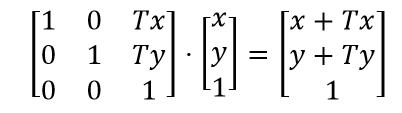
Translation transforms: “1.0, 0.0, 0.0, 1.0, OffsetX, OffsetY”

805-003


Skew transforms: “1.0, tan(SkewY), tan(SkewX), 1.0, 0.0, 0.0”

805-004


#804 – Specifying a MatrixTransform as a Simple String

You can specify an arbitrary transform to apply to an element by using a MatrixTransform element.  Below is an example of the XAML used to do this, showing the full logical tree.

        <Label Background="LightCoral" Content="The Earth" Margin="5"
               HorizontalAlignment="Center">
            <Label.LayoutTransform>
                <MatrixTransform>
                    <MatrixTransform.Matrix>
                        <Matrix M11="1.3" M12="0.1"
                                M21="0.1" M22="1.2"
                                OffsetX="5.0" OffsetY="6.0"/>
                    </MatrixTransform.Matrix>
                </MatrixTransform>
            </Label.LayoutTransform>
        </Label>

There’s a much more concise way of specifying this transform, however.  You can take advantage of a type converter provided for the LayoutTransform or RenderTransform properties, allowing you to specify the Matrix element for the transform as a simple string.  The string has the format M11,M12,M21,M22,OffsetX,OffsetY.  So we can simplify the above XAML to the following:

        <Label Background="LightCoral" Content="The Earth" Margin="5"
               HorizontalAlignment="Center"
               LayoutTransform="1.3,0.1,0.1,1.2,5.0,6.0"/>

#803 – Specifying an Arbitrary Transform with a MatrixTransform

You can transform user interface elements using the ScaleTransformRotateTransformTranslateTransform and SkewTransform objects.  Each of these transforms maps to a 3 x 3 transformation matrix that uses homogeneous coordinates to transform the element.

You can also specify any arbitrary transformation matrix directly, using the Matrix property of a MatrixTransform object.  The Matrix property is set to a Matrix struct, containing the following properties: M11, M12, M21, M22, OffsetX, and OffsetY.  This results in the transformation matrix:

803-001

        <Label Background="LightCoral" Content="The Earth" Margin="5" HorizontalAlignment="Center">
            <Label.LayoutTransform>
                <MatrixTransform>
                    <MatrixTransform.Matrix>
                        <Matrix M11="1.3" M12="0.1" M21="0.1" M22="1.2" OffsetX="5.0" OffsetY="6.0"/>
                    </MatrixTransform.Matrix>
                </MatrixTransform>
            </Label.LayoutTransform>
        </Label>

803-002

#802 – Transforms Do Not Affect an Element’s Margins

When you apply a 2D transform to a user interface element, the transform impacts only the element and everything inside of the element.  It therefore does not change the element’s margins.

In the example below, we have a Label element that has a margin of 5 separating it from its parent Border.  Notice that when we scale the second instance of the Label, it still retains the same margin.

    <StackPanel>
        <Border BorderBrush="Black" BorderThickness="3" HorizontalAlignment="Center">
            <Label Background="LightCoral" Content="Scale Me" Margin="5"/>
        </Border>
        <Border BorderBrush="Black" BorderThickness="3" HorizontalAlignment="Center">
            <Label Background="LightCoral" Content="Scale Me" Margin="5">
                <Label.LayoutTransform>
                    <ScaleTransform ScaleX="1.5"/>
                </Label.LayoutTransform>
            </Label>
        </Border>
    </StackPanel>

802-001

#800 – Transforms Do Not Affect ActualWidth and ActualHeight

Transforms do not change the values of the original element’s dimensions, as reported by the ActualWidth and ActualHeight properties.  This is true for both LayoutTransforms and RenderTransforms.

    <StackPanel>
        <Button Name="btn1" Content="Apollo" HorizontalAlignment="Center"
                Margin="5"/>

        <Button Name="btn2" Content="Apollo" HorizontalAlignment="Center"
                Margin="5">
            <Button.RenderTransform>
                <ScaleTransform ScaleX="1.5" ScaleY="2.0"/>
            </Button.RenderTransform>
        </Button>

        <Button Name="btn3" Content="Apollo" HorizontalAlignment="Center"
                Margin="5">
            <Button.LayoutTransform>
                <ScaleTransform ScaleX="1.5" ScaleY="2.0"/>
            </Button.LayoutTransform>
        </Button>

        <Button Content="Debug" Click="Button_Click" HorizontalAlignment="Center"
                Margin="10"/>
    </StackPanel>

800-001
Notice that when we inspect the elements in the debugger, they all have identical values for ActualWidth and ActualHeight.
800-002

#799 – How Transforms Are Combined

Because all transforms in WPF use homogeneous coordinates, combining transforms is accomplished simply by multiplying one or more 3 x 3 matrices together.

For example, suppose that we want to combine a rotation and a translation transform:

                <TransformGroup>
                    <RotateTransform Angle="30"/>
                    <TranslateTransform X="5.0" Y="10.0"/>
                </TransformGroup>

Recall that the 3 x 3 transformation matrix for rotation looks like:
799-001

And recall that the 3 x 3 transformation matrix for translation looks like:

799-002

To combine these two transforms together, we multiply the matrices, but in the opposite order from how they are listed:

799-005

For the example above, that works out to:

799-006

Multiplying any point by this final matrix will result in the point first being rotated and then translated.

In WPF, all of this works automatically behind the scenes.  You just specify in XAML the transforms that you want applied to your user interface elements and WPF calculates and stores the proper transformation matrix.

#798 – Rotation Transforms Using Homogeneous Coordinates

You can apply a rotation transform to a 2D point using a 2 x 2 transformation, multiplying it by a 2 x 1 point matrix.  This results in a second 2 x 1 point matrix that represents the transformed (rotated) point.

798-001

In WPF, however, rotation transforms are done using homogeneous coordinates, which means that we multiply a 3 x 3 transformation matrix by a 3 x 1 point matrix.

798-002

In the resulting 3 x 1 matrix, the first and second rows contain the x and y values of the transformed (rotated) point.

#797 – Scale Transforms Using Homogeneous Coordinates

You can apply a scale transform to a 2D point using a 2 x 2 transformation, multiplying it by a 2 x 1 point matrix.  This results in a second 2 x 1 point matrix that represents the transformed (scaled) point.

789-001


In WPF, however, scaling transforms are done using homogeneous coordinates, which means that we multiply a 3 x 3 transformation matrix by a 3 x 1 point matrix.

Untitled


In the resulting 3 x 1 matrix, the first and second rows contain the x and y values of the transformed (scaled) point.


#796 – WPF Transforms Use Homogeneous Coordinates

We saw that we can perform scale and rotation transforms on points in 2D by multiplying a 2 x 2 transformation by a 2 x 1 matrix representing a point.  A translation transform, however, could not be accomplished using a 2 x 2 matrix.  Instead, we multiply a 3 x 3 matrix by a 3 x 1 matrix that represents the 2D point.

795-001

In WPF, all 2D transforms are accomplished using a 3 x 3 transformation matrix and a 3 x 1 point matrix.  The 3 x 1 matrix contains the x and y components of the point in the first two rows and a value of 1 as the third row.  This is done so that we can easily combine scale, rotate and translation transforms, since they all use matrices of the same dimensions.

In representing a 2D point using a 3 x 1 matrix, WPF is making us of homogeneous coordinates, which involves adding a third dimension, represented by the third row of the point matrix.

#795 – How a Translation Transform Works

A 2D translation transform in WPF is accomplished by using a transformation matrix.  The transformation matrix is multiplied by another matrix representing a single 2D point to be transformed.  The resulting matrix describes the transformed point.

Unlike rotation and scaling transforms, we can’t perform a translation by multiplying a 2 x 2 matrix (representing the transform) by a 2 x 1 matrix (representing the point).  Instead, we multiple a 3 x 3 matrix by a 3 x 1 matrix, as shown below.

795-001

In this case, we represent the point (x, y) not by a 2 x 1 matrix, but by a 3 x 1 matrix where the third row is always 1.  The resulting 3 x 1 matrix then also contains a third row with a value of 1 and the new transformed (x, y) point in the first two rows.

Notice that we get what we expect for a translation.  Tx is added to x and Ty is added to y, representing a translation.