#1,206 – Changing Color of Custom Circular Progress

A couple of earlier posts (#1,155 and #1,156) demonstrated how to create a simple custom control that displays progress in a circular fashion. A reader of the blog asked how you would change the color of the progress indicator when it got to a certain value. The example below shows how to do that.

Below is the code for the indicator itself. This matches post #1,156 except that we’ve removed the static constructor that overrides the stroke and fill color of the indicator.

    public class CircularProgress : Shape
    {
        // Value (0-100)
        public double Value
        {
            get { return (double)GetValue(ValueProperty); }
            set { SetValue(ValueProperty, value); }
        }

        // DependencyProperty - Value (0 - 100)
        private static FrameworkPropertyMetadata valueMetadata =
                new FrameworkPropertyMetadata(
                    0.0,     // Default value
                    FrameworkPropertyMetadataOptions.AffectsRender,
                    null,    // Property changed callback
                    new CoerceValueCallback(CoerceValue));   // Coerce value callback

        public static readonly DependencyProperty ValueProperty =
            DependencyProperty.Register("Value", typeof(double), typeof(CircularProgress), valueMetadata);

        private static object CoerceValue(DependencyObject depObj, object baseVal)
        {
            double val = (double)baseVal;
            val = Math.Min(val, 99.999);
            val = Math.Max(val, 0.0);
            return val;
        }

        protected override Geometry DefiningGeometry
        {
            get
            {
                double startAngle = 90.0;
                double endAngle = 90.0 - ((Value / 100.0) * 360.0);

                double maxWidth = Math.Max(0.0, RenderSize.Width - StrokeThickness);
                double maxHeight = Math.Max(0.0, RenderSize.Height - StrokeThickness);

                double xStart = maxWidth / 2.0 * Math.Cos(startAngle * Math.PI / 180.0);
                double yStart = maxHeight / 2.0 * Math.Sin(startAngle * Math.PI / 180.0);

                double xEnd = maxWidth / 2.0 * Math.Cos(endAngle * Math.PI / 180.0);
                double yEnd = maxHeight / 2.0 * Math.Sin(endAngle * Math.PI / 180.0);

                StreamGeometry geom = new StreamGeometry();
                using (StreamGeometryContext ctx = geom.Open())
                {
                    ctx.BeginFigure(
                        new Point((RenderSize.Width / 2.0) + xStart,
                                  (RenderSize.Height / 2.0) - yStart),
                        true,   // Filled
                        true);  // Closed
                    ctx.ArcTo(
                        new Point((RenderSize.Width / 2.0) + xEnd,
                                  (RenderSize.Height / 2.0) - yEnd),
                        new Size(maxWidth / 2.0, maxHeight / 2),
                        0.0,     // rotationAngle
                        (startAngle - endAngle) > 180,   // greater than 180 deg?
                        SweepDirection.Clockwise,
                        true,    // isStroked
                        false);
                    ctx.LineTo(new Point((RenderSize.Width / 2.0), (RenderSize.Height / 2.0)), true, false);
                }

                return geom;
            }
        }
    }

Next is a snippet from the code-behind for a main window. This is just a click handler for a button that updates a property. (Note the use of SetProp method from post #1,205)

        private double _pctComplete = 0.0;
        public double PctComplete
        {
            get { return _pctComplete; }
            set { SetProp(ref _pctComplete, value); }
        }

        private void Button_Click(object sender, RoutedEventArgs e)
        {
            PctComplete = 0.0;

            DispatcherTimer timer = new DispatcherTimer();
            timer.Tick += (s, ea) =>
            {
                PctComplete += 1.0;
                if (PctComplete >= 100.0)
                    timer.Stop();
            };
            timer.Interval = new TimeSpan(0, 0, 0, 0, 150);  
            timer.Start();
        }

We then have a XAML fragment, where we define an instance of the progress indicator. We also set up a data trigger to set the Stroke and Fill properties to change color when they reach a certain level.

    <Window.Resources>
        <loc:GreaterThanConverter x:Key="greaterThanConverter"/>
        
        <Style x:Key="progChangeColor" TargetType="loc:CircularProgress">
            <Setter Property="Stroke" Value="Red"/>
            <Setter Property="Fill" Value="Red"/>
            <Style.Triggers>
                <DataTrigger Binding="{Binding PctComplete, Converter={StaticResource greaterThanConverter}, ConverterParameter=75}" Value="True">
                    <Setter Property="Stroke" Value="Green"/>
                    <Setter Property="Fill" Value="Green"/>
                </DataTrigger>
            </Style.Triggers>
        </Style>
    </Window.Resources>
    
    <StackPanel>
        <loc:CircularProgress
            Style="{StaticResource progChangeColor}"
             Height="100" Width="100" Margin="5"
             Value="{Binding PctComplete}"
             HorizontalAlignment="Center"/>
        <ProgressBar Maximum="100"
                 Value="{Binding PctComplete}"
                 Height="25" Margin="10"/>
        <Button Content="Start Timer" Click="Button_Click"
            HorizontalAlignment="Center"
            Padding="12,7"/>
    </StackPanel>

Note that we’re making use of a value converter that takes a value in (e.g. PctComplete) and outputs True when that value passes a certain point (e.g. 75). Here’s the code for that converter:

    public class GreaterThanConverter : IValueConverter
    {
        public object Convert(object value, Type targetType, object parameter, CultureInfo culture)
        {
            return ((double)value) > double.Parse(parameter as string);
        }

        public object ConvertBack(object value, Type targetType, object parameter, CultureInfo culture)
        {
            throw new NotImplementedException();
        }
    }

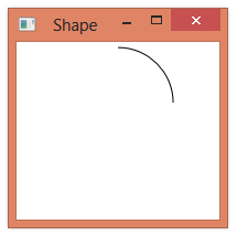
When everything is wired up and we run this, we see that the indicator starts out red.

And it then turns green when progress gets past 75%.

#1,151 – Custom Arc Shape, part III

In the previous example of a custom arc shape, we use the standard Stroke and StrokeThickness properties when rendering the shape.  Note, however, that when we increase the thickness of the stroke, part of the stroke lies outside of the boundaries of the shape.

1151-001

We can fix this problem by accounting for the stroke thickness in the drawing logic.  The updated code is shown below.

        protected override Geometry DefiningGeometry
        {
            get
            {
                double maxWidth = Math.Max(0.0, RenderSize.Width - StrokeThickness);
                double maxHeight = Math.Max(0.0, RenderSize.Height - StrokeThickness);
                //Console.WriteLine(string.Format("* maxWidth={0}, maxHeight={1}", maxWidth, maxHeight));

                double xStart = maxWidth / 2.0 * Math.Cos(StartAngle * Math.PI / 180.0);
                double yStart = maxHeight / 2.0 * Math.Sin(StartAngle * Math.PI / 180.0);

                double xEnd = maxWidth / 2.0 * Math.Cos(EndAngle * Math.PI / 180.0);
                double yEnd = maxHeight / 2.0 * Math.Sin(EndAngle * Math.PI / 180.0);

                StreamGeometry geom = new StreamGeometry();
                using (StreamGeometryContext ctx = geom.Open())
                {
                    ctx.BeginFigure(
                        new Point((RenderSize.Width / 2.0) + xStart,
                                  (RenderSize.Height / 2.0) - yStart),
                        false,
                        false);
                    ctx.ArcTo(
                        new Point((RenderSize.Width / 2.0) + xEnd,
                                  (RenderSize.Height / 2.0) - yEnd),
                        new Size(maxWidth / 2.0, maxHeight / 2),
                        0.0,     // rotationAngle
                        (EndAngle - StartAngle) > 180,   // greater than 180 deg?
                        SweepDirection.Counterclockwise,
                        true,    // isStroked
                        true);
                }

                return geom;
            }
        }

1151-002


#1,150 – Custom Arc Shape, part II

Below is code that implements a custom Shape to draw an arc.  The earlier code has been improved to:

  • Support elliptical arcs (height != width)
  • Add dependency properties for start and end angles

Start and end angles are automatically coerced to keep them within the range [0, 360).

    public class Arc : Shape
    {
        // Angle that arc starts at
        public double StartAngle
        {
            get { return (double)GetValue(StartAngleProperty); }
            set { SetValue(StartAngleProperty, value); }
        }

        // DependencyProperty - StartAngle
        private static PropertyMetadata startAngleMetadata =
                new PropertyMetadata(
                    0.0,     // Default value
                    null,    // Property changed callback
                    new CoerceValueCallback(CoerceAngle));   // Coerce value callback

        public static readonly DependencyProperty StartAngleProperty =
            DependencyProperty.Register("StartAngle", typeof(double), typeof(Arc), startAngleMetadata);

        // Angle that arc ends at
        public double EndAngle
        {
            get { return (double)GetValue(EndAngleProperty); }
            set { SetValue(EndAngleProperty, value); }
        }

        // DependencyProperty - EndAngle
        private static PropertyMetadata endAngleMetadata =
                new PropertyMetadata(
                    90.0,     // Default value
                    null,    // Property changed callback
                    new CoerceValueCallback(CoerceAngle));   // Coerce value callback

        public static readonly DependencyProperty EndAngleProperty =
            DependencyProperty.Register("EndAngle", typeof(double), typeof(Arc), endAngleMetadata);

        private static object CoerceAngle(DependencyObject depObj, object baseVal)
        {
            double angle = (double)baseVal;
            angle = Math.Min(angle, 359.9);
            angle = Math.Max(angle, 0.0);
            return angle;
        }

        protected override Geometry DefiningGeometry
        {
            get
            {
                double maxWidth = RenderSize.Width;
                double maxHeight = RenderSize.Height;

                double xStart = maxWidth / 2.0 * Math.Cos(StartAngle * Math.PI / 180.0);
                double yStart = maxHeight / 2.0 * Math.Sin(StartAngle * Math.PI / 180.0);

                double xEnd = maxWidth / 2.0 * Math.Cos(EndAngle * Math.PI / 180.0);
                double yEnd = maxHeight / 2.0 * Math.Sin(EndAngle * Math.PI / 180.0);

                StreamGeometry geom = new StreamGeometry();
                using (StreamGeometryContext ctx = geom.Open())
                {
                    ctx.BeginFigure(
                        new Point((maxWidth / 2.0) + xStart,
                                   (maxHeight / 2.0) - yStart),
                        false,
                        false);
                    ctx.ArcTo(
                        new Point((maxWidth / 2.0) + xEnd,
                                  (maxHeight / 2.0) - yEnd),
                        new Size(maxWidth / 2.0, maxHeight / 2),
                        0.0,     // rotationAngle
                        (EndAngle - StartAngle) > 180,   // greater than 180 deg?
                        SweepDirection.Counterclockwise,
                        true,    // isStroked
                        true);
                }

                return geom;
            }
        }
    }

We can use the Arc shape as shown below.

1150-001

#1,149 – Drawing an Arc in a Custom Shape

We can use a StreamGeometryContext to render some geometry in a custom Shape element that we can then use in XAML.  Below is an example that draws a simple arc from 0 degress to 90 degrees.  It uses a PolarPoint class to allow describing the arc start and finish as polar coordinates.  (A future post will allow a user to specify arc start and end).

    public class Arc : Shape
    {
        protected override Geometry DefiningGeometry
        {
            get
            {
                double maxWidth = RenderSize.Width;
                double maxHeight = RenderSize.Height;
                double maxRadius = Math.Min(maxWidth, maxHeight) / 2.0;

                PolarPoint arcStart = new PolarPoint(maxRadius, 0.0);
                PolarPoint arcFinish = new PolarPoint(maxRadius, 90.0);

                StreamGeometry geom = new StreamGeometry();
                using (StreamGeometryContext ctx = geom.Open())
                {
                    ctx.BeginFigure(
                        new Point((maxWidth / 2.0) + arcStart.X,
                                   (maxHeight / 2.0) - arcStart.Y),
                        false,
                        false);
                    ctx.ArcTo(
                        new Point((maxWidth / 2.0) + arcFinish.X,
                                  (maxHeight / 2.0) - arcFinish.Y),
                        new Size(maxRadius, maxRadius),
                        0.0,     // rotationAngle
                        false,   // greater than 180 deg?
                        SweepDirection.Counterclockwise,
                        true,    // isStroked
                        true);
                }

                return geom;
            }
        }
    }

Using the arc:

        <loc:Arc Stroke="Black" StrokeThickness="1"
                 Height="100" Width="100" Margin="5"
                 HorizontalAlignment="Center"/>

1149-001

#1,145 – Using RenderSize in Custom Shape

When drawing a geometry in a custom Shape element, you could draw using hard-coded coordinates.  It’s more common, however, to use the RenderSize property of the UIElement to render the object so that the geometry scales based on the size of the control.

Below, we create a custom shape that draws a diagonal line from the upper left corner of the control to the lower right.

    public class MyShape : Shape
    {
        protected override Geometry DefiningGeometry
        {
            get
            {
                double maxWidth = RenderSize.Width;
                double maxHeight = RenderSize.Height;

                StreamGeometry geom = new StreamGeometry();
                using (StreamGeometryContext ctx = geom.Open())
                {
                    ctx.BeginFigure(
                        new Point(0.0, 0.0),
                        false,
                        false);
                    ctx.LineTo(
                        new Point(maxWidth, maxHeight),
                        true,
                        false);
                }

                return geom;
            }
        }
    }

We can use the shape in XAML as follows:

    <StackPanel>
        <loc:MyShape Stroke="Black" StrokeThickness="1"
                     Height="50" Width="50"
                     HorizontalAlignment="Center"/>
    </StackPanel>

Now when we change the size of the underlying control, the geometry adjusts as well.

1145-001

1145-002

1145-003

#1,144 – Geometry in Custom Shape Doesn’t Automatically Scale

If you define a custom Shape by creating some Geometry, the resulting geometry will not automatically scale when shape’s size is changed.

Suppose that we have the following custom shape.

    public class MyShape : Shape
    {
        protected override Geometry DefiningGeometry
        {
            get
            {
                StreamGeometry geom = new StreamGeometry();
                using (StreamGeometryContext ctx = geom.Open())
                {
                    ctx.BeginFigure(
                        new Point(0.0, 0.0),
                        false,
                        false);
                    ctx.LineTo(
                        new Point(50.0, 50.0),
                        true,
                        false);
                }

                return geom;
            }
        }
    }

Placing this control in a StackPanel, it’s size is just large enough to accommodate the geometry.

1144-001

If we explicitly make the shape larger, the underlying geometry stays the same size.

1144-002

#1,143 – Coordinate System for StreamGeometry

You can use a StreamGeometry object, along with the StreamGeometryContext returned by its Open method, to draw simple geometric shapes.

When using the various methods of a StreamGeometryContext instance, you work with X and Y values.  The coordinate system used has the upper left corner of the drawing region at (0,0), with X values increasing from left to right and Y values increasing from top to bottom.

1143-001

Below, we have a custom shape that draws a line segment from (0,0) to (50,50) and then another line segment to (75,25).

    public class MyShape : Shape
    {
        protected override Geometry DefiningGeometry
        {
            get
            {
                return GetMyShapeGeometry();
            }
        }

        private Geometry GetMyShapeGeometry()
        {
            StreamGeometry geom = new StreamGeometry();
            using (StreamGeometryContext ctx = geom.Open())
            {
                ctx.BeginFigure(
                    new Point(0.0, 0.0),
                    false,    // is NOT filled
                    false);   // is NOT closed
                ctx.LineTo(
                    new Point(50.0, 50.0),
                    true,     // is stroked (line visible)
                    false);   // is not smoothly joined w/other segments
                ctx.LineTo(
                    new Point(75.0, 25.0),
                    true,     // is stroked (line visible)
                    false);   // is not smoothly joined w/other segments
            }

            return geom;
        }
    }

We can then use this shape from XAML.

    <Canvas>
        <loc:MyShape Canvas.Top="0" Canvas.Left="0"
                     Stroke="Black" />
    </Canvas>

1143-002

#240 – Shape vs. DrawingVisual

We’ve seen two ways to render custom 2D geometries–by inheriting from DrawingVisual and hosting in an UIElement or by inheriting from Shape and instancing your object directly in XAML.

You might wonder which of these methods to use for drawing custom 2D objects.

Shape is at a higher level of abstraction than DrawingVisualShape provides the following functionality, beyond what you get with DrawingVisual:

  • Derives from FrameworkElement, so you can include your subclass directly into a logical tree as a child of a Panel
  • Takes care of things like the Pen used to render the geometry (Stroke and StrokeThickness) and the Brush used to fill the interior of the geometry

Below is an example of including several instances of a custom Shape and specifying different stroke/fill properties for each instance.

	<StackPanel Orientation="Horizontal">
		<local:MyWeirdShape Stroke="Black" StrokeThickness="2" Fill="Orange"/>
		<local:MyWeirdShape Stroke="Red" StrokeThickness="1" Fill="DimGray"/>
		<local:MyWeirdShape Stroke="Blue" StrokeThickness="10" Fill="White"/>
	</StackPanel>

#239 – Creating a Custom Shape by Overriding the Shape Class

If you need a specialized shape that you can’t use any of the Shape subclasses to draw, you can create your own custom class that inherits from Shape.

You define the shape to be drawn by overriding the Shape.DefiningGeometry property.  In the get accessor, you create and return an instance of a Geometry.  In the example below, we create a new Geometry and then use the StreamGeometryContext to draw the geometry.

    public class MyWeirdShape : Shape
    {
        protected override Geometry DefiningGeometry
        {
            get { return GenerateMyWeirdGeometry(); }
        }

        private Geometry GenerateMyWeirdGeometry()
        {
            StreamGeometry geom = new StreamGeometry();
            using (StreamGeometryContext gc = geom.Open())
            {
                // isFilled = false, isClosed = true
                gc.BeginFigure(new Point(50.0, 50.0), false, true);
                gc.ArcTo(new Point(75.0, 75.0), new Size(10.0, 20.0), 0.0, false, SweepDirection.Clockwise, true, true);
                gc.ArcTo(new Point(100.0, 100.0), new Size(10.0, 20.0), 0.0, false, SweepDirection.Clockwise, true, true);
            }

            return geom;
        }
    }

Using the new object in XAML:

	<StackPanel>
		<local:MyWeirdShape Height="150" Width="150" Stroke="Black" StrokeThickness="2"/>
	</StackPanel>